Small robots have been household gadgets for decades, but until recently they’ve been little more than toys. With a limited range of motion and almost no interaction with their environment, a task as simple as moving from one point to another without bumping into something was too advanced for these early bots.
In the last few years, however, these “toys” have become far more sophisticated. Lifelike humanoid bowlers, dinosaurs with personalities, and robotic dogs that recognize spoken commands are now mainstream products. Even the old-fashioned interlocking plastic brick has gone high-tech with motors, sensors, and programmable circuits.

The miniaturization of these circuits and sensors has certainly played the biggest role in making small robots increasingly intelligent and capable, but a lesser-known supporting player is the humble servomechanism. More commonly known as a servo, it’s essentially an electric motor combined with positional feedback. The servo knows how far it has turned and is able to respond to electronic commands such as: “Turn 60° left of center.” This feature makes the servo ideal for arm and leg joints, sensor scanners, and other robotic accouterments.
With the increasing demand for robot kits and toys, the performance and diversity of servos has been growing. There are now jumbo-sized servos (about 7 centimeters long), micro servos (some as small as 3 grams), servos with metal gears (for extra-heavy loads), and all kinds of torques, speeds, and packagings. There’s even a SERVO Magazine that covers the burgeoning community of robot-building, servo-hacking hobbyists.
But like any electronic device, servos have limitations. They can’t drive a robot wheel, for example, because servos don’t rotate continuously like a normal motor. Instead, to keep their design and construction simple, they allow rotation only through 180° or so (although some advanced models can do up to 360°). Providing both the position control of a servo and the speed control of a motor would make the servo’s electronics and signaling too complex. After all, if a robot’s design calls for a wheel or other continuously rotating device, a traditional motor can always do the job.
Ironically, though, thanks to improving technology and falling prices, servos are probably the cheapest type of geared motor on the market, especially after factoring in the speed control circuitry (an H-bridge) that comes built-in with every servo. In fact, servos often provide higher power in a more compact package than comparably priced motors. The only catch is that a servo is still a servo: It can’t spin continuously the way a normal motor can.
Luckily, there’s a relatively easy fix for this problem. Because servos are basically a motor with a feedback loop, simply disconnecting the feedback opens the loop. Without feedback to tell the servo it has reached a desired position, it will just keep on turning. The servo effectively becomes a continuously rotating motor that just happens to have a speed control circuit and gearbox conveniently attached to it.
Although this hack is a great way to save money—just convert old unused servos instead of buying new motors—the full conversion process isn’t quite so simple. There are additional complications to deal with, such as the cylindrical stop on the output gear that prevents full rotation. The feedback circuit that detects the angle of rotation (usually a simple potentiometer) also has to be anchored to a neutral position so that it doesn’t accidentally generate feedback signals, causing the servo to turn spontaneously.
A variety of tutorials explain how to get around these problems (search for “modify servo continuous rotation”), and some manufacturers even sell servos pre-modified for continuous rotation. Unfortunately, after starting a project for a two-wheeled self-balancing robot (like a mini-Segway), I consulted a variety of these tutorials and found them inadequate. None addressed the issues of a metal-geared servo, which I happened to be using, nor did they explain the difference between driving the motor with a traditional H-bridge circuit rather than a servo controller.
After struggling through these obstacles, I was finally able to complete the modifications, but not without some confusion and setbacks. To save others from the same kind of trouble, I’ve written the following tutorial on how to modify a servo for continuous rotation. While similar to existing tutorials of this kind, it goes into a bit more detail than most and, given the wide variety of servos available, having another perspective on the process couldn’t hurt.
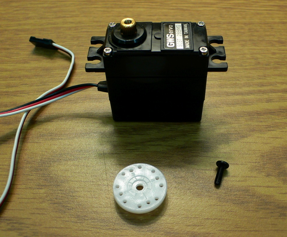
This tutorial deals specifically with the standard-sized GWS S03T servo, a rather high-end model with metal gears, dual ball bearings, and an extra-high gear ratio that provides almost double the torque of a typical servo. The metal gears improve strength, while the ball bearings ensure smoother rotation and better centering. Note that the addition of these features does not alter the basic design of the servo, which is remarkably similar across manufacturers and models, so the advice offered in this tutorial should be widely applicable.

The first step is to remove whatever horn or arm happens to be installed on the servo. (The S03T ships from the factory with a standard wheel attached.)
Next, remove the body screws. Be careful not to strip the grooves off the screw heads.

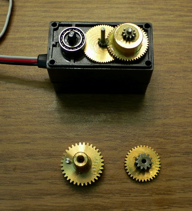
After removing the body screws, pull off the top of the case to expose the gears.

Now remove the output gear and the top center gear, taking care not to lose any of the tiny parts. In this particular servo, removing the output gear should expose one of the two ball bearings. (The other should have come off when removing the top of the case and is most likely still lodged inside of it, underneath the opening.)
Turn the output gear over and you should see a plastic slot. This piece connects the potentiometer to the geartrain so that every turn of the servo also turns the potentiometer, thus providing positional feedback. This is how the servo knows when it has reached the desired angle and should stop turning.

The goal here is to transform the servo into a motor, so the feedback needs to be disabled. To do so, simply remove the plastic slot; it should pop right off.

Now, turn the output gear right-side up and note the small cylindrical stop. It mechanically prevents continuous rotation of servo, so it has to be removed. If this gear were made of plastic, the stop could be removed rather easily using a tiny saw, wire cutters, or perhaps even fine-grained sand paper.
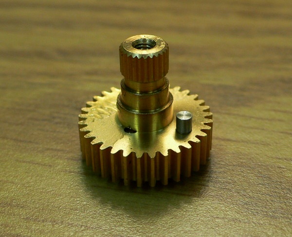
With a metal gear, however, removal is more difficult. After many attempts at yanking the stop out of its socket, I eventually had to grind it clean off using a rotary tool. (Be careful not to grind too far into the gear itself. You can see in the picture that I accidentally shaved off part of the gear shaft’s base.)

Note that other tutorials describe an additional step at this point: Replacing the feedback potentiometer with a voltage divider, composed of two resistors, to fool the servo circuitry into thinking the potentiometer is still connected and fixed at the center position. This feat is rather tricky, though, because the exact values for the resistors must be determined by calibrating the servo at its center position and then measuring the resistance across the old potentiometer. An alternative approach, one that works on this servo and probably many others as well, is to manually rotate the potentiometer shaft to its center position, then simply glue it in place! This will achieve the same effect of convincing the servo that it hasn’t reached the requested angle and will thus continue to rotate.
After removing the gear stop, disconnecting the feedback potentiometer, and fixing it in place (either electrically with a voltage divider or mechanically with glue), the modifications are complete. You can now reassemble the servo and send it the usual PWM signals from a servo controller. These signals formerly told the gears which angle to move to; now they control how fast the gears should rotate and in which direction.
But the story does not end here. The original servo motor driver circuits are still in the loop, and this could cause problems. The electronics in a servo are usually designed for the sporadic, off-and-on operation of normal servo usage, not the continuous spinning of a motor. They might not be able to handle the constant activity and could eventually burn out. Also, the controllers that generate PWM signals for a servo typically have higher latency than a standard DC motor driver, especially if it’s a serial servo controller that has to perform the extra step of translating RS-232 signals.
So what’s the solution? Simply rip out all of the electronics from the servo, thereby converting it to a simple geared motor. You will then have to drive it with a standard H-bridge motor controller rather than a servo controller, but you will likely gain faster response time and minimize the chances of early burn-out.
To begin the lobotomy, pry off the bottom of the servo’s case.

Next, turn the servo upside down and note the location of its circuitry.

Cut away the hard tacky glue that holds the circuitry in place, then carefully pull it out.

Now cut off the electronics to complete the lobotomy. (The black piece shown in the picture connects the potentiometer to the output gear. It fell out when removing the electronics, but since potentiometer feedback isn’t needed after this conversion, it can be discarded.)

At this point, you have a choice to make. You can either splice the wires together, or you can remove the motor’s wires entirely. The first option is simpler but might be unreliable depending on how you splice the wires. The latter option requires more work, but it gives you the option of using your own wires, and you can solder them for a more permanent hold. I chose to remove the motor’s wires and attach the original external servo wires directly to the motor. The first step was to scrape off the hard tacky glue off the terminals, then use a soldering iron to melt the solder and remove the wires.

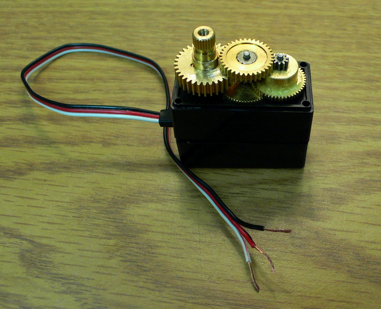
Now you can solder the external servo wires—or any other wires, depending on your needs—directly to the motor. (My soldering job in this picture was quite messy; don’t think I’m trying to pass this off as a good example of a soldered joint!)

Finally, reassemble the servo case and put the gears back on. (Don’t forget to return the two ball bearings to their original locations.) You now have a servo-sized motor with a high-torque metal geartrain in a nice tidy package!
Here’s a short video of the motor in action.
[flashvideo file=http://vocaro.com/trevor/blog/wp-content/uploads/2009/06/servo.mp4 width=450 height=430 /]
Thanks to Adam Borrell for his helpful advice that made this tutorial possible.
I guess you probably tried this, but I was able to remove the little metal stop thing from the gear without grinding it off by simply putting the gear in a bench vice and yanking it out with some rather long pliers.
Tried one without the pot, no motor. tried it with pot, works a treat – I only had plastic gears, but once I’d cut away the pot drive, I switched it on, made sure it was dead central for zero movement, then filled pot with with cyano. No chance of it moving now. Thanks!!!
Impara la pronuncia
Good morning. But are we “sure veramenti” that works as it says? I didn’t see the demonstration but it seems strange to me that it could work that way !! Completely eliminate the control electronics …. I am perplexed. The penultimate photo, I doubt these connections. I personally would have connected the pwm signal to the motor casing. ……..
thanks, this worked great with rds5160…
now i like to try it with the super500 with
a vnh5019,
the super500 servo has the same 3 wires (
power, gnd and control) and 2 extra wires
connecting to battery;
the vnh5019 can take 5v to 18v( max. consistent volt)
the battery pack can be connected to the vnh5019, so
the super500 will need 18v to move 50Nm,
my question is can i apply the same technique
from your demo or my rds5160 to the super500
and ignore the 2 extra power wires from the super500
thanks in advance for your suggestion+opinion