When adding a folder to an Xcode project, you can add it as a group or as a reference.
What’s the difference, and why would you choose one over the other? Each has advantages and disadvantages, some of which are quite subtle.
Groups
With groups, Xcode stores in the project a reference to each individual file. This can lead to problems:
The size and complexity of the underlying project file (project.pbxproj) can grow significantly, especially with multiple targets. Each new target has to duplicate all of the references. You also have to remember to set the proper target membership for each file. Plus there is a greater likelihood of SCM merge conflicts due to the larger and more complex project file.
Groups may bear no resemblance at all to the folder hierarchy on disk. You can have project folders in the Finder that don’t even exist in the Xcode project, and vice versa. Because of the mismatch, locating files can get confusing.
If you move a file or rename it outside of Xcode, the reference breaks and the file turns red. File management becomes a real pain.
In exchange for these annoyances, groups give you some advantages:
You can pick and choose which files on disk you want to appear in the project. There may be auxiliary files such as documentation that you don’t want to appear in the Xcode Project Navigator.
You get fine-grained control over target membership. You can, for example, exclude a single file from a target.
When building the product, Xcode flattens the group hierarchy and dumps all the files in the top level of the product’s bundle. You don’t have to specify the location in the hierarchy. For example, instead of:
[UIImage imageNamed:@"Images/Icons/GoPago"];
you can just do:
[UIImage imageNamed:@"GoPago"];
But this does mean you have to resolve conflicts if two images happen to share the same name.
Folder References
Folder references are simpler. You can spot a folder reference because it shows up in blue instead of yellow.
The benefits of folder references are:
Xcode only stores a reference to the folder. All of its files and subfolders are automatically added to the project. This keeps the project file smaller and simpler, with less chance of merge conflicts.
If you rename, delete, or move a file in the file system, Xcode automatically updates the folder reference to reflect the change. File management is thus far easier.
Because the folder hierarchy in the project matches the hierarchy on disk, they will not diverge over time and cause confusion.
You don’t have to worry about name conflicts because the directory structure is preserved in the product bundle. Two files can share the same name as long as they live in different directories.
So why don’t we always use folder references?
Target membership is coarse-grained. Either all of the files in the folder are in the target, or none are. (On the other hand, if you actually want all files in the folder to have membership, this could be more of a pro than a con.)
There is no way to hide individual files from the project navigator. Either they all appear or none do. (Again, this could in fact be an advantage because there’s no way for a file in the folder reference to be accidentally left out of the project.)
When loading a resource, you must specify the full path. Instead of:
[UIImage imageNamed:@"GoPago"];
you must do:
[UIImage imageNamed:@"Images/Icons/GoPago"];
And if you change the file’s location on disk, you must remember to update the code.
An image stored as a folder reference will not work with Interface Builder! When editing, IB is able to find the image file and allows you to select it, but when it generates the XIB, it strips the folder location, which prevents it from being found. The result is a blank image and a runtime error:
Could not load the "MyImage.png" image referenced from a nib in the bundle with identifier "com.mytest.MyProject"
Conclusion
The fact that Interface Builder can’t work with images in (sub)folder references is a dealbreaker. And being able to select the target membership for individual files””a feature only provided by groups””can be very useful. For these reasons, you will find that groups are far more common in practice, and it is the option I recommend. You just have to live with the fact that if you move the files around on disk, you’ll have to manually update the Xcode project to match.
That said, it’s unfortunate that Xcode doesn’t offer better support for folder references. I wish I could use them more often, as I hate having to keep my project view in sync with the filesystem, but the IB problem keeps me away. And I almost never need groups, since my projects typically have only one target, and pretty much everything in my project folder gets bundled into the product. Maybe one day Apple will fix the IB bug and my wish can come true.
When deadlines loom, even skilled and experienced programmers can get a little sloppy. The pressure to ship may cause them to cut corners and look for a quick and easy solution, even if that solution is sure to cause trouble later on. Eventually, their coding style devolves into copy and paste programming, a lamentable tactic that involves cherry-picking snippets of code from a past project and putting them to use in the current one. Of course, the proper solution is to factor out the code into some kind of reusable library, but due to time constraints, it’s simply duplicated wherever it’s needed. Any bugs in the original code have now spread to a dozen different places in a dozen different projects. It’s an algorithm for chaos.
Yet in the world of iPhone applications, copy and paste programming seems to be disturbingly common. The fact that so many iPhone apps are short-term, one-off projects doesn’t help, but the situation has been aggravated even more by Apple’s security restrictions. In particular, dynamic linking to any shared library that doesn’t ship with the OS is strictly forbidden. One could argue that this rule is a necessary side-effect of the iPhone’s sandboxing security model, but even workarounds such as consolidating code into a static shared library are extraordinarily difficult. Another contributing factor is that the iPhone API is still relatively immature, and developers too often require custom code to fill in its gaps.
This situation has transformed more than a few iPhone programmers into copy and paste programmers. When they inevitably encounter some limitation with the iPhone API, the typical response is:
Now imagine what happens when a thousand iPhone developers find the same snippet. Suddenly the problems of copy and paste programming have gone global. Offline, a bug in a single snippet of code may infect a dozen projects; online, it can spread to thousands.
As a reluctant copy and paste iPhone programmer myself, I’ve witnessed this scenario first-hand. I recently encountered a limitation with a certain iPhone class—UIImage—and I found in a discussion forum what seemed to be a popular, well-regarded solution. The code snippet was the first hit in a Google search, and many readers had replied with thanks to its author. However, a bit of testing showed that it worked for most images but completely failed for others. By the time I stumbled upon it, the buggy code had probably spread to countless programs already.
In the process of finding the bug and posting the fix, I ended up writing a substantial amount of additional code to address various other annoyances related to UIImage. The complete listing is available for download below. Though it won’t solve the copy and paste problem, it should be a welcome remedy for other iPhone developers who have run into similar obstacles.
Background
Programming for the iPhone, a highly graphical device, necessarily involves a substantial amount of image manipulation. Its SDK therefore provides an abstraction called UIImage that handles much of the effort in importing and drawing images. For example, imagine you want to load a JPEG file, scale it down to icon size, and give it rounded corners. These tasks may require tens or even hundreds of lines of code on other platforms, but on the iPhone, it’s only a matter of instantiating a UIImage, passing it to a UIImageView of the appropriate size, and setting the cornerRadius property.
Despite its ease of use, or perhaps because of it, UIImage suffers from some serious limitations. Key among these is its lack of support for resizing the image, a feature that is normally handled dynamically by its companion, the UIImageView component. However, should an iPhone application need to reduce the size of an image for storage or for exchange with an external entity (such as a web server), the UIImage class is insufficient.
Of course, UIImage is not the only means of image manipulation on the iPhone. It ships with a rather sophisticated graphics API, known as Quartz 2D, that offers low-level control of bitmap data. Clearly, the functionality for resizing an image exists, although taking advantage of it is not straightforward and requires the developer to write non-trivial code. How best to accomplish this task has been the source of much confusion and debate, particularly in forums such as iPhone Dev SDK:
This is crazy. I know there are threads that touch on this already, but none of them have led me to the answer. I can’t believe that it is really this difficult!
I have done lots of searching for a way to resize images via the iPhone SDK and I have come across a few methods which work but the resulting image does not look nearly as good as if you took the full resolution image and told it to draw inside a rectangle.
These discussions have resulted in countless code snippets that claim to resize a UIImage, but many of them contain bugs, or they simply leave out functionality such as EXIF orientation support, an absolute necessity when dealing with photographs taken by the iPhone’s camera. For instance, a particularly popular code snippet for UIImage resizing incorrectly processes alpha information, resulting in a pink tint for certain image files.
Image resized correctly
Image resized with buggy code
A Better Way to Resize Images
The following sections describe yet another collection of source code for resizing UIImage objects. Functionally, it is similar to code samples that can be found elsewhere on the Internet in discussion forums and blogs, but it consolidates their features into a self-contained, reusable package and offers several notable improvements:
Additional methods for cropping images, generating thumbnails, and more.
Implemented as Objective-C categories to facilitate reuse. With categories, you can simply plop the code into your project, import a header file, and all of your UIImage objects will automatically have access to the new methods.
Bugs that commonly plague other code of this type have been found and fixed. The categories have been vetted in a large, real-world iPhone app, and they contain no known bugs.
The code has been simplified as much as possible and is more thoroughly documented.
The source code to the categories can be downloaded from the links below or as a single archive. If you are an experienced iPhone programmer, you can probably grab the files and start using them right away. Continue reading for more detail on how to apply them, as well as a run-down of the problems that prompted their creation.
Extends the UIImage class with helper methods for working with alpha layers (transparencies).
UIImage+Alpha
The Alpha category is perhaps not as directly useful as the others, though it provides some necessary functionality that they build upon. Its methods include:
- (BOOL)hasAlpha;
Tells whether the image has an alpha layer.
- (UIImage *)imageWithAlpha;
Returns a copy of the image, adding an alpha channel if it doesn’t already have one. An alpha is required when adding transparent regions (e.g., rounded corners) to an image. It may also be necessary when loading certain kinds of image files that are not directly supported by Quartz 2D. For example, if you load a JPEG using imageNamed:, the resulting UIImage will have 32 bits per pixel with the first 8 bits unused (kCGImageAlphaNoneSkipFirst). But if you take the same image and save it in BMP format, and load it exactly the same way, the UIImage will have 24 bits per pixel (kCGImageAlphaNone), which is unsupported in Quartz 2D. Trying to render it to a graphics context will cause run-time errors. The obvious way around this problem is to make sure you only load image files that produce a Quartz-compatible pixel format. (A complete list is available in the Supported Pixel Formats section of the Quartz 2D Programming Guide.) If for some reason this is not possible, adding an alpha channel to the UIImage at runtime may also work.
Returns a copy of the image with a transparent border of the given size added around its edges. This solves a special problem that occurs when rotating a UIImageView using Core Animation: Its borders look incredibly ugly. There’s simply no antialiasing around the view’s edges. Luckily, adding a one-pixel transparent border around the image fixes the problem. The extra border moves the visible edges of the image to the inside, and because Core Animation interpolates all inner pixels during rotation, the image’s borders will magically become antialiased. This trick also works for rotating a UIButton that has a custom image. The following before-and-after video shows the technique in action. (The top square is the original image; the bottom square has a one-pixel transparent border.)
UIImage+RoundedCorner
With the release of iPhone OS 3.0, a new Core Animation feature called cornerRadius became available. When applied to a layer, it makes the corners soft and round, just the thing for achieving a Web 2.0 or Mac OS X look-and-feel. For example, if you have a UIButton with a custom image like this:
The fun stops there. The cornerRadius setting only affects the run-time appearance of the layer. As soon as you save the image or send it over the network, the rounded corners go away. Also, if you animate the layer, perhaps by making it rotate, the cornerRadius property mysteriously reverts to zero, giving the image sharp corners again. This is a confirmed bug (#7235852) in iPhone OS 3.0 and 3.1.
To fix this problem, the RoundedCorner category can apply rounded corners to a UIImage permanently. It modifies the image data itself, adding an alpha layer if necessary. Not only does this work around the Core Animation bug, it also preserves the rounded corner effect when exporting the UIImage to a file or network stream, assuming that the output format supports transparency.
Creates a copy of the image, adding rounded corners of the specified radius. If borderSize is non-zero, a transparent border of the given size will also be added. (The primary purpose of this parameter is to work around the aforementioned aliasing problem that occurs when rotating an image view.) The implementation is based on code by Björn Sållarp.
UIImage+Resize
Resizing a UIImage is more complicated than it may seem. First, there’s simply the matter of learning Quartz 2D—a somewhat complex, low-level API. A mistake in a single parameter can suddenly affect thousands of pixels, yielding unexpected results like the pink tint problem shown previously.
Another issue to consider is the quality of the resulting image. By default, Quartz 2D applies a fast but not-so-high-quality interpolation algorithm when scaling images up or down. The effect is especially noticeable when reducing an image to a very small size, perhaps for an icon or thumbnail representation. The aliasing caused by the algorithm transforms smooth lines into jagged edges. Faces become a pixelated mess.
To illustrate, the following image is the result of squeezing a 1024×516-pixel JPEG (courtesy of PD Photo) into a 320×200-pixel UIImageView with automatic resizing enabled:
Note the serrated edges along the wings. To counteract the unsightliness, Quartz 2D can be configured for a different scaling algorithm by calling CGContextSetInterpolationQuality. Here is the same image, pre-scaled using the kCGInterpolationHigh option, and displayed in the same UIImageView:
The jaggies are now gone, replaced with smoother, cleaner lines.
Yet another obstacle, one of particular importance to iPhone developers, is image orientation. When a user takes a snapshot with the iPhone’s camera, the image is not upright but is in fact rotated 90 degrees counterclockwise. The reason is because the iPhone’s camera is positioned in a way that makes up (from the lens’s perspective) point to the left-hand side of the camera. The iPhone’s camera software knows this and therefore adds a special flag to the image data that indicates how the pixels should be rotated to produce the correct orientation. The software employs the same tactic when the user takes a picture in landscape mode (i.e., holding the phone sideways). It can rotate the image without having to apply a transformation across millions of pixels. Instead, it simply changes the orientation flag. Components such as UIImageView automatically read this flag—stored in the imageOrientation property of UIImage—and apply the proper rotation at run-time when displaying the image.
Unfortunately, as soon as you dip into the low-level Quartz 2D API, which has no knowledge of the high-level UIImage class, the orientation information is lost. An image resize algorithm written using this API will need to be provided with the orientation and perform the rotation explicitly.
The Resize category solves each of these problems while incorporating additional handy features. Its methods include:
- (UIImage *)croppedImage:(CGRect)bounds;
Returns a copy of the image that is cropped to the given bounds. The bounds will be adjusted using CGRectIntegral, meaning that any fractional values will be converted to integers.
Returns a copy of the image reduced to the given thumbnail dimensions. If the image has a non-square aspect ratio, the longer portion will be cropped. If borderSize is non-zero, a transparent border of the given size will also be added. (The primary purpose of this parameter is to work around the aforementioned aliasing problem that occurs when rotating an image view.) Finally, the quality parameter determines the amount of antialiasing to perform when scaling the image.
Returns a resized copy of the image. The quality parameter determines the amount of antialiasing to perform when scaling the image. Note that the image will be scaled disproportionately if necessary to fit the specified bounds. In other words, the aspect ratio is not preserved.
This method, as well as all other methods described here that perform resizing, takes into account the orientation of the UIImage and transforms the pixels accordingly. The resulting image’s orientation will be up (UIImageOrientationUp), regardless of the current orientation value. The code to perform this transformation is based in part on the following sources:
UIImageView offers a remarkably helpful ability: It can resize displayed images while preserving their aspect ratio. The manner of preservation depends on a setting known as the content mode. For example, if a large JPEG (courtesy of PD Photo) is displayed in a small view with the content mode set to Center (UIViewContentModeCenter), only a portion of the image is visible:
To include the entire image, the view’s content can be scaled to fit within the bounds (UIViewContentModeScaleToFill). Note that Scale To Fill does not preserve the aspect ratio, resulting in a squashed image:
To scale the image without changing the aspect ratio, one option is to shrink the content until it fits entirely within the bounds (UIViewContentModeScaleAspectFit). Although this option shows the full image, it has the side-effect of not filling the entire view:
(Note that any area not covered by the image in Aspect Fill mode is actually transparent. It’s colored gray here to show the view boundary.)
Another aspect-preserving option is to shrink the content just enough to fit the smaller dimension within the view. The larger dimension (in this case, the length) will be cropped:
The correct choice of content mode depends, of course, on the desired appearance and the nature of the source image.
Because these modes are so useful, equivalent functionality has been rolled into the Resize category. Scale To Fill is the default behavior of resizedImage:interpolationQuality:, while resizedImageWithContentMode: supports both Aspect Fit and Aspect Fill. (Other content modes, such as Left and Bottom Right, were left unimplemented because they are rarely used.)
License
All code presented here is free for both personal and commercial use, with or without modification. No warranty is expressed or implied.
A common annoyance on the Internet is having to enter the same account information over and over again. If you want to post a comment on a blog, or join a discussion group, or simply register an account at any given web site, you have to type the same basic details each time: a user name, a password (twice!), probably an email address, and maybe additional information such as your time zone or date of birth. And usually, whenever you return to the site, you have enter your account credentials again and hope that you’ve remembered the right password.
This digital identity problem is not new, and many software utilities have been written with the aim of solving it—or at least simplifying it. 1Password is a typical example. It automates the process of filling out forms and can manage your online accounts, so you never have to re-enter a user name or password.
Still, I’ve got 275 logins stored in 1Password. That means I’ve had to create 275 different accounts on 275 different web sites. Wouldn’t it be better to unify these accounts under a single web-wide identity that I can manage myself?
I’m certainly not the first to pose this question, and in fact, a solution is already here. It’s called OpenID. It replaces your usual registration and login details with a single URL. For example, if you have an account on Yahoo!, you can enable your Yahoo! account for OpenID access. Then, if you ever need to register or sign in at a web site, you simply enter your Yahoo! credentials and you’re done—assuming, of course, that the web site supports OpenID. You don’t have to create a new account or keep track of yet another user name and password pair.
In addition to Yahoo!, a variety of OpenID providers is available. If you have an account with one of them, then you already have an OpenID. Simply choose the provider you like best and use their URL wherever OpenID is supported.
There’s only one drawback. If you’re going to have a permanent, universal ID, wouldn’t you want it to be bit more personal? Why use some company’s ID, like myspace.com/username or username.blogspot.com, when you could have your very own username.com? You can easily convert a domain that you’ve registered for yourself into an OpenID. Here’s how.
First, assume that your name is Joe Random, and you’ve registered a domain called randomdomain.com. Let’s also assume that you’ve set up a server for the domain through a web hosting provider. The server will need to support PHP and allow .htaccess configuration. Any decent hosting provider includes these bells and whistles by default, so you shouldn’t need to do anything special.
Decide on a user name and password. They can be anything you like, such as joerandom and randompassword.
Decide on a name for the realm. The realm is simply an identity for your OpenID domain. It can be anything you like, such as “Joe’s OpenID” or “My Very Own OpenID Provider”.
Create an MD5 hash of the user name, password, and realm. If you use Mac OS X, Linux, or another UNIX-based operating system, open a terminal and type:
echo -n 'username:realm:password' | openssl md5
Replace username, realm, and password with the values you have chosen. Windows users should download John Walker’s utility and run:
md5.exe -d"username:realm:password"
The output should be a long string of hexadecimal characters, something like:
66999343281b2624585fd58cc9d36dfc
Save this string; you will need to copy and paste it in a subsequent step.
Download phpMyID and extract the files to a local directory.
Locate the MyID.config.php file and open it in a text editor.
Change the auth_username field to the user name you have chosen.
Change the auth_password field to the MD5 hash that you generated in the previous step.
Change the auth_realm field to the realm you have chosen. Don’t forget to remove the # to uncomment the line.
This step is optional but recommended. In the same MyID.config.php file, there is an array of registration information, such as your email address, postal code, and so on. These details will be sent along with your OpenID when registering a new account at a web site. For example, if you live in Madrid, you would enter ES as your two-letter country code and Europe/Madrid as your time zone. Again, don’t forget to remove the # to uncomment each line.
Locate the htaccess file, which you extracted from the phpMyID distribution, and open it in a text editor.
Uncomment all of the lines for Option 1 by removing the #.
Rename the htaccess file to .htaccess
On the server that hosts randomdomain.com, create a directory called OpenID at the root of the domain. You should be able to access it by visiting randomdomain.com/OpenID.
Upload the .htaccess, MyID.php, and MyID.config.php files to this directory.
Verify that phpMyID is working correctly by visiting http://randomdomain.com/OpenID/MyID.config.php. You should see the realm that you have chosen and a Login link. Follow the link and you should be prompted for the user name and password you have chosen. Enter them, and you should see a message saying that you are logged in. If so, all is well; if not, follow the troubleshooting steps in the phpMyID README file.
Decide on the exact URL you want for your OpenID. This will be the actual ID that you provide to a web site when logging in. It can be anything on the domain, but you should probably keep it simple, like randomdomain.com/joe or simply randomdomain.com. If you ever want to allow an additional OpenID, such as randomdomain.com/jane, the former is obviously the better choice.
Specify an OpenID server and delegate by creating an index.html file (or modify an existing one) at the URL you have chosen. You will need to add <link> elements that point to your phpMyID installation. For example, your HTML file will look something like this:
You now have a shiny new OpenID! Test it by creating an account at one of the many sites that support OpenID. Or, if you already have an account at one of these sites, you can link it to your new OpenID. Simply follow the instructions provided at the site.
Though this may look like a complicated procedure, the individual steps are all pretty simple. phpMyID handles most of the real work for you. And of course you can customize many of the steps to suit your needs. For instance, you don’t have to upload phpMyID to a directory called OpenID; you can upload it anywhere you like. But if you choose a different location, then you will need to change the links in the HTML file accordingly.
Like most universities, UCI has a strict set of rules for formatting and typesetting doctoral dissertations. The rules fall into the usual categories of margin, typeface, and layout guidelines, as well as some unique requirements for copyright declarations, the signature page, a curriculum vitae, and so on. A complete list is provided in the UCI Thesis and Dissertation Manual.
With so many requirements in this 43-page manual, starting out on the first draft of a dissertation can be rather daunting for Ph.D. students, especially since improper formatting could get the manuscript rejected by the University Archives. A word processor template would virtually eliminate this problem, but according to the AGS website, UCI provides no officially-sanctioned template for dissertations. Each student must format their manuscript from scratch, leading to duplicated effort and wasted time.
A few enterprising students have responded to this problem by creating unofficial UCI dissertation templates. They are designed specifically for LaTeX, a document preparation system favored by EECS and ICS grad students for its extensive support for mathematical equations, high-quality typesetting, and similarity to a computer programming language. By starting off with such a template as the foundation, writing a UCI dissertation essentially becomes a fill-in-the-blank process as LaTeX takes care of the table of contents, list of figures, and other formatting details automatically.
Xianping Ge created the first such template in 2002. It was later refined by Jeffery von Ronne and is now available on Vivek Haldar’s blog. Working separately, I started with Xianping’s original template and made my own set of clean-ups and enhancements with help from Mark Panahi. It improves upon Jeffrey’s version by adding a CV template, extensive comments to help the Ph.D. student fill-in and customize the template, and various minor fixes. In addition, I reviewed every aspect of the template to make sure that its output conforms to the Dissertation Manual as closely as possible.
The template can be downloaded by following the link below, which leads to a ZIP file containing the template, its LaTeX class file, a makefile for generating a PDF of the dissertation, a sample bibliography, and a “readme” file with more details on how to use the template. The link will be updated as new versions of the template become available.
Small robots have been household gadgets for decades, but until recently they’ve been little more than toys. With a limited range of motion and almost no interaction with their environment, a task as simple as moving from one point to another without bumping into something was too advanced for these early bots.
In the last few years, however, these “toys” have become far more sophisticated. Lifelike humanoid bowlers, dinosaurs with personalities, and robotic dogs that recognize spoken commands are now mainstream products. Even the old-fashioned interlocking plastic brick has gone high-tech with motors, sensors, and programmable circuits.
The miniaturization of these circuits and sensors has certainly played the biggest role in making small robots increasingly intelligent and capable, but a lesser-known supporting player is the humble servomechanism. More commonly known as a servo, it’s essentially an electric motor combined with positional feedback. The servo knows how far it has turned and is able to respond to electronic commands such as: “Turn 60° left of center.” This feature makes the servo ideal for arm and leg joints, sensor scanners, and other robotic accouterments.
With the increasing demand for robot kits and toys, the performance and diversity of servos has been growing. There are now jumbo-sized servos (about 7 centimeters long), micro servos (some as small as 3 grams), servos with metal gears (for extra-heavy loads), and all kinds of torques, speeds, and packagings. There’s even a SERVO Magazine that covers the burgeoning community of robot-building, servo-hacking hobbyists.
But like any electronic device, servos have limitations. They can’t drive a robot wheel, for example, because servos don’t rotate continuously like a normal motor. Instead, to keep their design and construction simple, they allow rotation only through 180° or so (although some advanced models can do up to 360°). Providing both the position control of a servo and the speed control of a motor would make the servo’s electronics and signaling too complex. After all, if a robot’s design calls for a wheel or other continuously rotating device, a traditional motor can always do the job.
Ironically, though, thanks to improving technology and falling prices, servos are probably the cheapest type of geared motor on the market, especially after factoring in the speed control circuitry (an H-bridge) that comes built-in with every servo. In fact, servos often provide higher power in a more compact package than comparably priced motors. The only catch is that a servo is still a servo: It can’t spin continuously the way a normal motor can.
Luckily, there’s a relatively easy fix for this problem. Because servos are basically a motor with a feedback loop, simply disconnecting the feedback opens the loop. Without feedback to tell the servo it has reached a desired position, it will just keep on turning. The servo effectively becomes a continuously rotating motor that just happens to have a speed control circuit and gearbox conveniently attached to it.
Although this hack is a great way to save money—just convert old unused servos instead of buying new motors—the full conversion process isn’t quite so simple. There are additional complications to deal with, such as the cylindrical stop on the output gear that prevents full rotation. The feedback circuit that detects the angle of rotation (usually a simple potentiometer) also has to be anchored to a neutral position so that it doesn’t accidentally generate feedback signals, causing the servo to turn spontaneously.
A variety of tutorials explain how to get around these problems (search for “modify servo continuous rotation”), and some manufacturers even sell servos pre-modified for continuous rotation. Unfortunately, after starting a project for a two-wheeled self-balancing robot (like a mini-Segway), I consulted a variety of these tutorials and found them inadequate. None addressed the issues of a metal-geared servo, which I happened to be using, nor did they explain the difference between driving the motor with a traditional H-bridge circuit rather than a servo controller.
After struggling through these obstacles, I was finally able to complete the modifications, but not without some confusion and setbacks. To save others from the same kind of trouble, I’ve written the following tutorial on how to modify a servo for continuous rotation. While similar to existing tutorials of this kind, it goes into a bit more detail than most and, given the wide variety of servos available, having another perspective on the process couldn’t hurt.
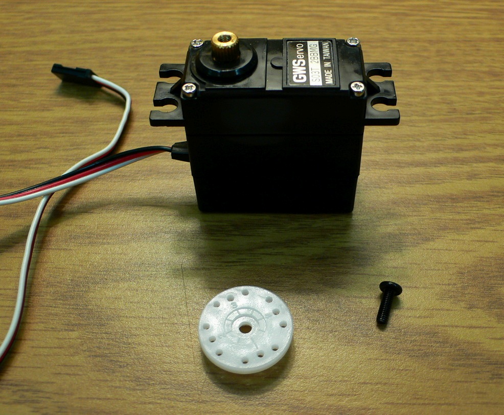
This tutorial deals specifically with the standard-sized GWSS03T servo, a rather high-end model with metal gears, dual ball bearings, and an extra-high gear ratio that provides almost double the torque of a typical servo. The metal gears improve strength, while the ball bearings ensure smoother rotation and better centering. Note that the addition of these features does not alter the basic design of the servo, which is remarkably similar across manufacturers and models, so the advice offered in this tutorial should be widely applicable.
The first step is to remove whatever horn or arm happens to be installed on the servo. (The S03T ships from the factory with a standard wheel attached.)
Next, remove the body screws. Be careful not to strip the grooves off the screw heads.
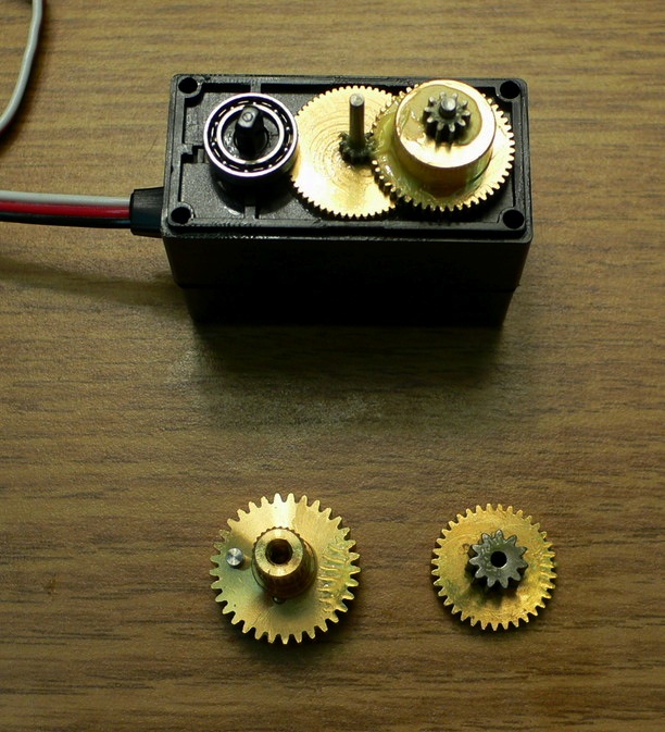
After removing the body screws, pull off the top of the case to expose the gears.
Now remove the output gear and the top center gear, taking care not to lose any of the tiny parts. In this particular servo, removing the output gear should expose one of the two ball bearings. (The other should have come off when removing the top of the case and is most likely still lodged inside of it, underneath the opening.)
Turn the output gear over and you should see a plastic slot. This piece connects the potentiometer to the geartrain so that every turn of the servo also turns the potentiometer, thus providing positional feedback. This is how the servo knows when it has reached the desired angle and should stop turning.
The goal here is to transform the servo into a motor, so the feedback needs to be disabled. To do so, simply remove the plastic slot; it should pop right off.
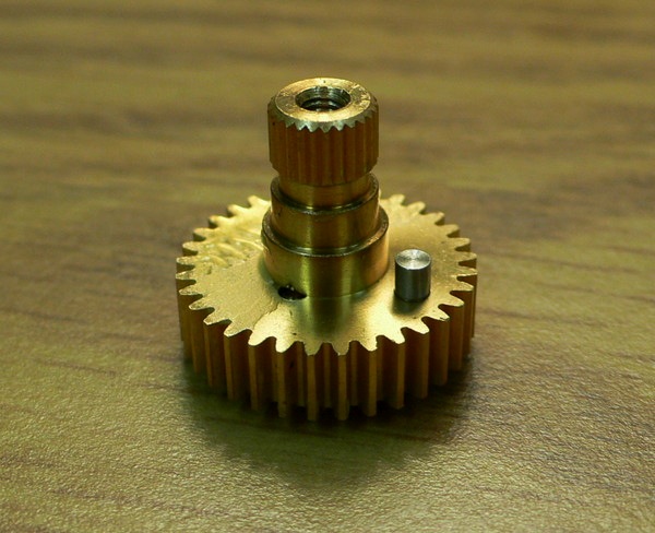
Now, turn the output gear right-side up and note the small cylindrical stop. It mechanically prevents continuous rotation of servo, so it has to be removed. If this gear were made of plastic, the stop could be removed rather easily using a tiny saw, wire cutters, or perhaps even fine-grained sand paper.
With a metal gear, however, removal is more difficult. After many attempts at yanking the stop out of its socket, I eventually had to grind it clean off using a rotary tool. (Be careful not to grind too far into the gear itself. You can see in the picture that I accidentally shaved off part of the gear shaft’s base.)
Note that other tutorials describe an additional step at this point: Replacing the feedback potentiometer with a voltage divider, composed of two resistors, to fool the servo circuitry into thinking the potentiometer is still connected and fixed at the center position. This feat is rather tricky, though, because the exact values for the resistors must be determined by calibrating the servo at its center position and then measuring the resistance across the old potentiometer. An alternative approach, one that works on this servo and probably many others as well, is to manually rotate the potentiometer shaft to its center position, then simply glue it in place! This will achieve the same effect of convincing the servo that it hasn’t reached the requested angle and will thus continue to rotate.
After removing the gear stop, disconnecting the feedback potentiometer, and fixing it in place (either electrically with a voltage divider or mechanically with glue), the modifications are complete. You can now reassemble the servo and send it the usual PWM signals from a servo controller. These signals formerly told the gears which angle to move to; now they control how fast the gears should rotate and in which direction.
But the story does not end here. The original servo motor driver circuits are still in the loop, and this could cause problems. The electronics in a servo are usually designed for the sporadic, off-and-on operation of normal servo usage, not the continuous spinning of a motor. They might not be able to handle the constant activity and could eventually burn out. Also, the controllers that generate PWM signals for a servo typically have higher latency than a standard DC motor driver, especially if it’s a serial servo controller that has to perform the extra step of translating RS-232 signals.
So what’s the solution? Simply rip out all of the electronics from the servo, thereby converting it to a simple geared motor. You will then have to drive it with a standard H-bridge motor controller rather than a servo controller, but you will likely gain faster response time and minimize the chances of early burn-out.
To begin the lobotomy, pry off the bottom of the servo’s case.
Next, turn the servo upside down and note the location of its circuitry.
Cut away the hard tacky glue that holds the circuitry in place, then carefully pull it out.
Now cut off the electronics to complete the lobotomy. (The black piece shown in the picture connects the potentiometer to the output gear. It fell out when removing the electronics, but since potentiometer feedback isn’t needed after this conversion, it can be discarded.)
At this point, you have a choice to make. You can either splice the wires together, or you can remove the motor’s wires entirely. The first option is simpler but might be unreliable depending on how you splice the wires. The latter option requires more work, but it gives you the option of using your own wires, and you can solder them for a more permanent hold. I chose to remove the motor’s wires and attach the original external servo wires directly to the motor. The first step was to scrape off the hard tacky glue off the terminals, then use a soldering iron to melt the solder and remove the wires.
Now you can solder the external servo wires—or any other wires, depending on your needs—directly to the motor. (My soldering job in this picture was quite messy; don’t think I’m trying to pass this off as a good example of a soldered joint!)
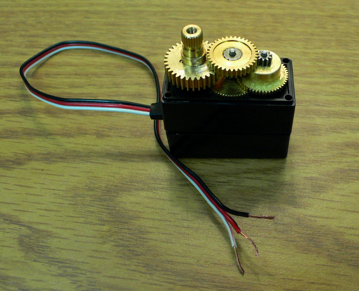
Finally, reassemble the servo case and put the gears back on. (Don’t forget to return the two ball bearings to their original locations.) You now have a servo-sized motor with a high-torque metal geartrain in a nice tidy package!
When I’m at home, my MacBook Pro is hooked up to an external display, a couple of hard drives, and other peripherals. When I need to go on the road, I put it to sleep, unplug all the peripherals, and away I go.
There’s only one problem: Unplugging a hard drive can corrupt its filesystem if it’s still mounted. To prevent that from happening, I wrote a script that automatically unmounts all drives. As an added bonus, the script fails if any of those drives are busy and can’t be unmounted, warning me to take additional action before hitting the road. Here it is:
tell application “Finder”
eject (every disk whose ejectable is true)
end tell
In most cases, this simple script works great, but it suffers from a few drawbacks:
It ejects not only hard drives, but optical discs as well, which is usually not what I want.
It won’t eject remotely mounted drives, such as NFS or AFP mounts.
It won’t work if Finder is not running, which may be the case for PathFinder users like myself.
To fix these issues, I split the script into two parts, one for local drives and one for remote drives, and I rewrote it so that optical discs would be left alone. Here’s the part that unmounts local drives:
-- Set this list to the names of the local drives
-- you want to unmount
set local_drives to [“Backup drive”, “Clone”]
repeat with drive in local_drives
set drive to “/Volumes/” & drive
set driveExists to false
try -- Ignore AppleScript warnings
do shell script “test -d ” & ¬
quoted form of drive
-- Test completed successfully; drive exists
set driveExists to true
end try
if driveExists then
-- Eject the drive
do shell script "umount " & ¬
quoted form of drive
end if
end repeat
And here’s the part that unmounts the remote drives:
-- Set this list to the names of the remote drives
-- you want to unmount
set remote_drives to [“DreamHost”, “DOC”]
repeat with drive in remote_drives
set drive to “/Volumes/” & drive
do shell script “umount ” & ¬
quoted form of drive
end repeat
I don’t eject optical drives, but if for some reason you need to do so, here’s how:
-- This will eject the optical disc in the
-- primary (built-in) drive
do shell script “drutil -drive 1 eject”
-- This will eject all discs in all optical drives
do shell script “drutil eject”
As the only open-source processor that supports the XSLT 2.0 specification, Saxon is becoming indispensable. I use it in my HR-XSL project, and the new functions and features of XSLT 2.0 have helped make the code a lot simpler.
A typical way of running Saxon is via Ant, which offers built-in support for XSLT processors. Its Xslt task defaults to the Xalan processor, but because this task understands the TrAX API, switching to Saxon is trivial. All you need to do is put Saxon’s JAR on the classpath. (This works because Saxon declares support for the TransformerFactory service in its manifest. When TrAX finds a match for this service, it knows which processor to use.)
But there’s a problem here. Xalan also supports TrAX, so it specifies the TransformerFactory service, as well. Thus it becomes a contest. The first processor listed on the classpath wins!
Now, one would think this wouldn’t be an issue. Xslt’s classpath attribute trumps the system’s classpath, right? Unfortunately, that’s not how it works—as discussed in the Ant FAQ—and as a result, you get unpredictable behavior: Your Ant script may or may not use Saxon depending on whether Xalan happens to be in your system’s classpath. This can be a real problem if, for example, you’ve used Fink to install Ant, which places Xalan on the system classpath by default.
All right, so that’s bad. Is there an easy way to solve this dilemma? How about the <factory> element of the Xslt task? It specifies a particular transformer factory to use, rather than letting TrAX instantiate the first one it happens to find. With this element, you should easily be able to force Ant to use Saxon, like this:
Alas, this also fails to work. For some reason, Ant always throws a ClassNotFoundException when you try to use the <factory> element this way. (See bug #41314 for more details.)
This was starting to hurt. I didn’t want my HR-XSL users submitting bug reports just because Ant couldn’t find Saxon. I needed a way to ensure that Saxon would run every time.
After following a number of dead ends, I finally found a solution. The trick is to set the Java property javax.xml.transform.TransformerFactory to Saxon’s transformer factory class. The TrAX implementation in Ant happens to look for this property and, if set, it will use the specified class rather than whatever it discovers on the classpath.
The hard part, surprisingly, is how to set the property. Ant provides no mechanism for changing Java’s system properties, so I rely instead on a custom Java class that extends and replaces Ant’s default TrAX handler. Just before a transformation occurs, it sets the transform factory property to net.sf.saxon.TransformerFactoryImpl, forcing Saxon to be used, then it restores the previous setting when the transformation is complete. (Restoring the property prevents conflicts with other XSLT-related Ant tasks, such as FOP.)
Once this class has been compiled, you tell Ant to use it via the processor attribute. For example, if the custom class is called SaxonLiaison (to reflect the class that it overrides, TraXLiaison), you’d call the Xslt task like this:
Most people know that when you sell or give away a computer, you should format its hard drive to make sure your sensitive information doesn’t fall into the wrong hands. And most of those people know that formatting a drive doesn’t actually erase all the data. Instead, you should use a special utility that overwrites every block of data on the drive. And a smaller portion of those people know that overwriting a block just once isn’t enough. If you really want to be safe, you should apply the Gutmann method, which overwrites every data block 35 times. And an even smaller portion of those people know that the Gutmann method is a myth.
I had always thought that the idea of overwriting the same data block 35 times was a bit dubious. (Why would 35 times be secure but 34 times not be?) And yet, most disk utilities provide an option to erase a hard drive 35 times over.
In a recent Slashdot article, I discovered a comment that shed some light on this issue. User Psionicist wrote (with typos faithfully reproduced):
I would like to take the oppertunity here to debunk a very common myth regarding hard drive erasure.
You DO NOT have to overwrite a file 35 times to be “safe”. This number originates from a misunderstanding of a paper about secure file erasure, written by Gutmann.
The 35 patterns/passes in the table in the paper are for all different hard disk encodings used in the 90:s. A single drive only use one type of encoding, so the extra passes for another encoding has no effect at all. The 35 passes are maybe useful for drives where the encoding is unknown though.
For new 2000-era drives, simply overwriting with random bytes is sufficient.
Here’s an epilogue by Gutmann for the original paper:
Epilogue In the time since this paper was published, some people have treated the 35-pass overwrite technique described in it more as a kind of voodoo incantation to banish evil spirits than the result of a technical analysis of drive encoding techniques. As a result, they advocate applying the voodoo to PRML and EPRML drives even though it will have no more effect than a simple scrubbing with random data. In fact performing the full 35-pass overwrite is pointless for any drive since it targets a blend of scenarios involving all types of (normally-used) encoding technology, which covers everything back to 30+-year-old MFM methods (if you don’t understand that statement, re-read the paper). If you’re using a drive which uses encoding technology X, you only need to perform the passes specific to X, and you never need to perform all 35 passes. For any modern PRML/EPRML drive, a few passes of random scrubbing is the best you can do. As the paper says, “A good scrubbing with random data will do about as well as can be expected”. This was true in 1996, and is still true now.
Looking at this from the other point of view, with the ever-increasing data density on disk platters and a corresponding reduction in feature size and use of exotic techniques to record data on the medium, it’s unlikely that anything can be recovered from any recent drive except perhaps one or two levels via basic error-cancelling techniques. In particular the the drives in use at the time that this paper was originally written have mostly fallen out of use, so the methods that applied specifically to the older, lower-density technology don’t apply any more. Conversely, with modern high-density drives, even if you’ve got 10KB of sensitive data on a drive and can’t erase it with 100% certainty, the chances of an adversary being able to find the erased traces of that 10KB in 80GB of other erased traces are close to zero.
So it seems my suspicions have been confirmed: You do not need to erase a hard drive 35 times before selling it on eBay. A quick zeroing out of the data is sufficient.
Out of the blue, iMovie decided to stop working for me. I’d launch it, and it would immediately quit. Not crashing, just quitting. (No crash log was generated.) The dock icon wouldn’t even appear.
I knew it wasn’t a problem with the iMovie application itself because when I switched to another user account on the same machine, iMovie ran fine. It had to be something in my home directory that was causing the problem.
Normally, simply getting rid of any preferences or caches fixes this sort of problem. I checked my account and found these:
~/Library/iMovie/
~/Library/Caches/iMovie HD/
~/Library/Preferences/com.apple.iMovie.plist
~/Library/Preferences/com.apple.iMovie3.plist
Unfortunately, moving them out of my Library directory didn’t change a thing. iMovie was still quitting on launch. Frustrated, I took my PowerBook to the local Apple Store for some advice, but even the “genius” at the bar wasn’t able to help. I returned home thinking that I’d have to reinstall Mac OS X before iMovie would ever work again.
I decided to give iMovie one last try. On a whim, I dragged its icon out of the Applications folder and into my Desktop, then launched it from there. Imagine my shock when iMovie started up! I quit, moved the icon back to Applications, and launched iMovie again. It still worked! Everything was back to normal.
I have no idea why dragging iMovie out of the Applications folder solved the problem. In fact, it shouldn’t have worked. But it did. Assuming this is not some obscure and one-in-a-zillion issue, it may affect other Mac apps, not just iMovie, so I’m posting this tip in the hope that it might help others who encounter the same problem I did.
TomTom Navigator 5 is a marvelous piece of software that can turn a PDA into a GPS navigation system. At $180, it’s somewhat expensive, but if you already have a PDA and get a cheap GPS receiver, you can end up saving hundreds of dollars over traditional stand-alone navigators.
For a few months now, I’ve been using it with my Treo 650, which means in addition to making calls, tracking finances, playing games, and surfing the web, my little smartphone keeps me from getting lost, too! I no longer have to ask for directions or look them up on the Internet; I just hop in the car, give Navigator an address, and it tells me exactly where to turn.
One of the more useful features in Navigator is that when you arrive at an interesting location, you can save your current GPS coordinates as a “Favorite.” You can then return to your Favorite at a later date without having to give Navigator an address. This feature is especially useful for remote locations that might not have an actual street address to begin with.
For instance, on a trip to South Dakota last week, my wife and I stayed at my parents’ cabin, which happens to be pretty deep in the woods, so I marked its location in Navigator as a Favorite. It wasn’t that I was worried about finding my way back; instead, I wanted to remember the coordinates of the cabin so that I could easily look them up in Google Earth when I returned home.
When I got back, I discovered that extracting those GPS coordinates was anything but easy. The Navigator 5 software won’t display the coordinates of a Favorite, and it doesn’t offer any documented way of uploading a Favorite to a computer. That meant I had to find an undocumented way.
After scouring numerous discussion boards and various websites, I finally cobbled together enough information on how to extract the GPS coordinates of a Favorite from TomTom Navigator 5. To save others from the trouble I went through, I’m posting a step-by-step guide below.
Convert the Favorite into a Point of Interest (POI).
Go to Change Preferences, then Manage POI, and choose Add POI Category.
Type a name for the new Favorites category. (“Favorites” sounds like a good choice.)
Choose a marker.
Choose Add POI, then select the Favorites category.
Choose Favorite and select the Favorite you want to convert to a POI.
Transfer the POI file to your computer. The easiest way to do this is with the FileZ utility.
Launch FileZ, then view the contents of the external card.
There should be a directory there called region-Map, where region is the map you are currently using (e.g., “Plains”).
Open that directory by tapping on the little triangle.
Look for a file ending with “OV2” and having the same name as the POI category you created in the previous step (e.g., “Favorites.ov2”).
Transfer this file to your computer. The easiest way to do this is to tap the file to select it, then tap the Send button and choose the Bluetooth option. This will shoot the file through the air onto your computer (assuming, of course, that your computer supports Bluetooth, as all good computers do). If not, you can choose the VersaMail option to email yourself the file, or use any other means at your disposal.
Extract the contents of the POI file. The next step is to convert the OV2 file from its original binary form into something that mere mortals can read. The easiest way to do this is at the GPS Visualizer website, which provides a convenient front-end for the GPSBabel software.
For the input file format, choose “TomTom POI file”.
For the output file format, choose “Textual Output”.
Select the file (e.g., Favorites.ov2) that you transferred to your computer in the previous step.
Click the “Convert the file” button.
That’s it! You should now see a list of your Favorites. The first column is the name of the Favorite; the second and third columns are its longitude and latitude. (The fourth column in parentheses is the location in UTM coordinates.) For example:
Cabin N44 58.663 W103 35.017 (12T 617600 4890373)
Now that you know the coordinates of your Favorite, you can use them any way you wish. For instance, you can copy and paste them directly into Google Earth’s search box, and it will immediately fly you there.